Asus P5E3 Premium WiFi-AP@n – страница 6
Инструкция к Материнской Плате Asus P5E3 Premium WiFi-AP@n
BIOS EHCI Hand-off [Enabled]
Allows you to enable the support for operating systems without an EHCI hand-off
Conguration options: [Disabled] [Enabled]
Port 64/60 Emulation [Disabled]
Allows you to enable or disable the I/O port 60h/64h emulation support. This item
should be enabled for the complete USB keyboard legacy support for non-USB
aware OSes.
Conguration options: [Disabled] [Enabled]
Legacy USB Support [Auto]
Allows you to enable or disable the support for legacy USB devices. Setting to
[Auto] allows the system to detect the presence of USB devices at startup. If
detected, the USB controller legacy mode is enabled. If no USB device is detected,
the legacy USB support is disabled.
Conguration options: [Disabled] [Enabled] [Auto]
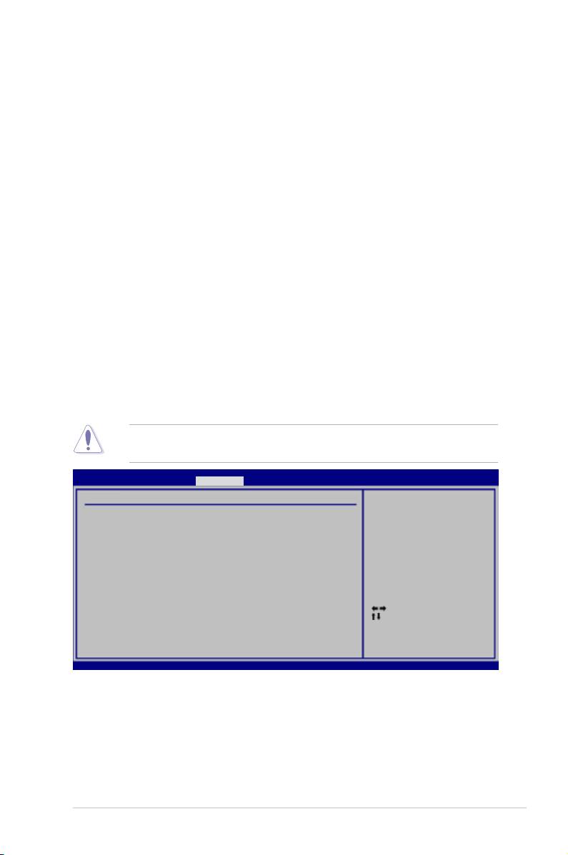
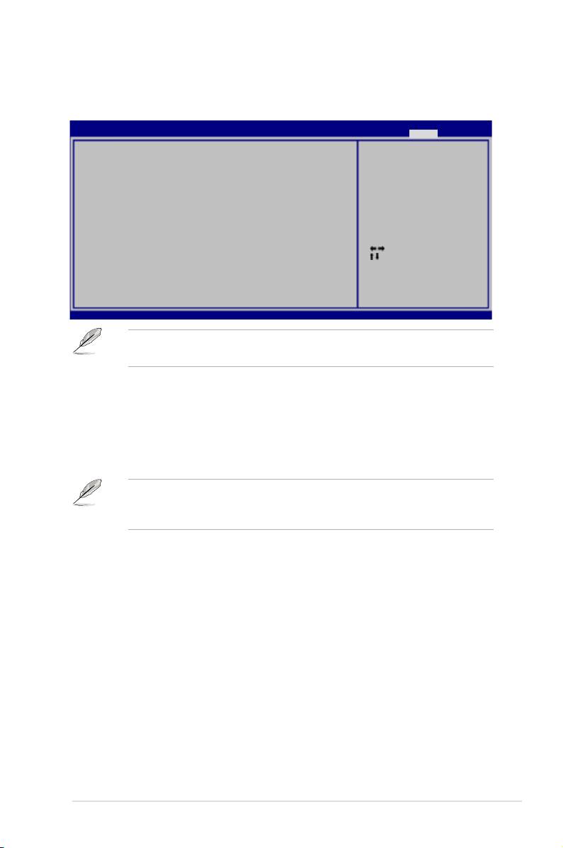
4.5.5 PCIPnP
The PCIPnP menu items allow you to change the advanced settings for PCI/PnP
devices.
Take caution when changing the settings of the PCIPnP menu items. Incorrect
eld values can cause the system to malfunction.
BIOS SETUP UTILITY
Advanced
Advanced PCI/PnP Settings
NO: lets the BIOS
congure all the
WARNING: Setting wrong values in below sections
devices in the system.
may cause system to malfunction.
YES: lets the
Plug And Play O/S [NO]
operating system
congure Plug and
Play (PnP) devices not
required for boot if
your system has a Plug
and Play operating
system.
Select Screen
Select Item
+-
Change Option
F1 General Help
F10 Save and Exit
ESC Exit
v02.61 (C)Copyright 1985-2007, American Megatrends, Inc.
Plug And Play O/S [NO]
When set to [NO], BIOS congures all the devices in the system. When set to
[YES] and if you install a Plug and Play operating system, the operating system
congures the Plug and Play devices not required for boot.
Conguration options: [NO] [YES]
ASUS P5E3 Premium/WiFi-AP @n 4-29

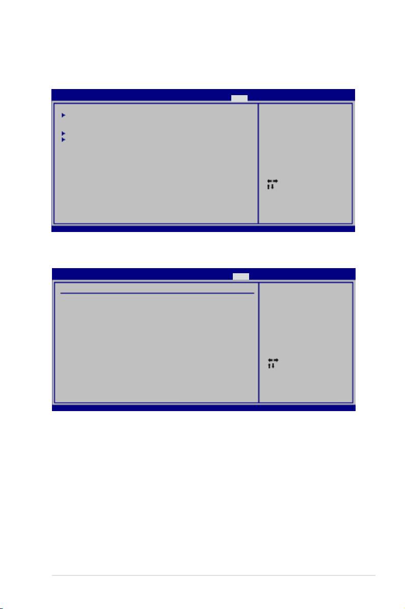
4.6 Power menu
The Power menu items allow you to change the settings for the Advanced
Power Management (APM). Select an item then press <Enter> to display the
conguration options.
BIOS SETUP UTILITY
Main Ai Tweaker Advanced Power Boot Tools Exit
Select the ACPI state
Suspend Mode [Auto]
used for System
Repost Video on S3 Resume [Disabled]
Suspend.
ACPI 2.0 Support [Disabled]
ACPI APIC Support [Enabled]
APM Conguration
Hardware Monitor
Select Screen
Select Item
+-
Change Option
F1 General Help
F10 Save and Exit
ESC Exit
v02.61 (C)Copyright 1985-2007, American Megatrends, Inc.
4.6.1 Suspend Mode [Auto]
Allows you to select the Advanced Conguration and Power Interface (ACPI) state
to be used for system suspend.
Conguration options: [S1 (POS) Only] [S3 Only] [Auto]
4.6.2 Repost Video on S3 Resume [Disabled]
Determines whether to invoke VGA BIOS POST on S3/STR resume.
Conguration options: [Disabled] [Enabled]
4.6.3 ACPI 2.0 Support [Disabled]
Add additional tables as per ACPI 2.0 specications.
Conguration options: [Disabled] [Enabled]
4.6.4 ACPI APIC Support [Enabled]
Allows you to enable or disable the Advanced Conguration and Power Interface
(ACPI) support in the Advanced Programmable Interrupt Controller (APIC). When
set to [Enabled], the ACPI APIC table pointer is included in the RSDT pointer list.
Conguration options: [Disabled] [Enabled]
4-30 Chapter 4: BIOS setup

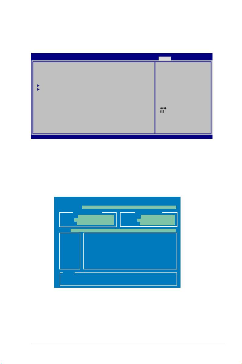
4.6.5 APM Conguration
BIOS SETUP UTILITY
Power
APM Conguration
<Enter> to select
whether or not to
Restore on AC Power Loss [Power Off]
restart the system
after AC power loss.
Power On By RTC Alarm [Disabled]
Power On By External Modems [Disabled]
Power On By PCI Devices [Disabled]
Power On By PCIE Devices [Disabled]
Power On By PS/2 Keyboard [Disabled]
Energy Star 4.0C Support [Disabled]
Select Screen
Select Item
+-
Change Option
F1 General Help
F10 Save and Exit
ESC Exit
v02.61 (C)Copyright 1985-2007, American Megatrends, Inc.
Restore On AC Power Loss [Power Off]
When set to [Power Off], the system goes into off state after an AC power loss.
When set to [Power On], the system goes on after an AC power loss. When set to
[Last State], the system goes into either off or on state, whatever the system state
was before the AC power loss.
Conguration options: [Power Off] [Power On] [Last State]
Power On By RTC Alarm [Disabled]
Allows you to enable or disable RTC to generate a wake event. When this item
is set to [Enabled], the items RTC Alarm Date/ RTC Alarm Hour/ RTC Alarm
Minute/ RTC Alarm Second will become user-congurable with set values.
Conguration options: [Disabled] [Enabled]
Power On By External Modems [Disabled]
This allows either settings of [Enabled] or [Disabled] for powering up the computer
when the external modem receives a call while the computer is in Soft-off mode.
Conguration options: [Disabled] [Enabled]
The computer cannot receive or transmit data until the computer and
applications are fully running. Thus, connection cannot be made on the rst
try. Turning an external modem off and then back on while the computer is off
causes an initialization string that turns the system power on.
Power On By PCI Devices [Disabled]
Allows you to enable or disable the PME to wake up from S5 by PCI devices.
Conguration options: [Disabled] [Enabled]
Power On By PCIE Devices [Disabled]
Allows you to enable or disable the PCIE devices to generate a wake event.
Conguration options: [Disabled] [Enabled]
ASUS P5E3 Premium/WiFi-AP @n 4-31

Power On By PS/2 Keyboard [Disabled]
Allows you to disable the Power On by PS/2 keyboard function or set specic keys
on the PS/2 keyboard to turn on the system. This feature requires an ATX power
supply that provides at least 1A on the +5VSB lead.
Conguration options: [Disabled] [Space Bar] [Ctrl-Esc] [Power Key]
Energy Star 4.0C [Disabled]
Allows you to enable or disable the Energy Star 4.0C support. When enabled, the
PS/2 and USB device wake-up function under S3 state and the Marvell LAN, PS/2
and USB device wake-up function under S4/S5 state will not be supported, saving
more energy to pass the Energy Star 4.0C regulations.
Conguration options: [Disabled] [Enabled]
4.6.6 Hardware Monitor
BIOS SETUP UTILITY
Power
Hardware Monitor
CPU Temperature
CPU Temperature [42ºC/107.5ºF]
CPU Fan Speed [3068RPM]
CPU Fan Control [Full Speed]
MB Temperature [32ºC/89.5ºF]
Chassis Fan 1 Speed [N/A]
Chassis Fan 2 Speed [N/A]
Chassis Fan 3 Speed [N/A]
Chassis Fan 4 Speed [N/A]
Chassis Fan Controls [Full Speed]
Select Screen
CPU Voltage [ 1.264V]
Select Item
3.3V Voltage [ 3.264V]
+-
Change Field
5V Voltage [ 5.088V]
F1 General Help
12V Voltage [12.040V]
F10 Save and Exit
ESC Exit
v02.61 (C)Copyright 1985-2007, American Megatrends, Inc.
CPU Temperature [xxxºC/xxxºF]
The onboard hardware monitor automatically detects and displays the CPU
temperature. Select [Ignored] if you do not wish to display the detected
temperatures.
CPU Fan Speed [xxxxRPM] or [Ignored] / [N/A]
The onboard hardware monitor automatically detects and displays the CPU
fan speed in rotations per minute (RPM). If the fan is not connected to the
motherboard, the eld shows [N/A].
CPU Fan Control [Full Speed]
Allows you to select the CPU fan control mode.
Conguration options: [Full Speed] [Prole] [Manual] [Fix Speed]
4-32 Chapter 4: BIOS setup

The following item appears only when you set the CPU Fan Control item to
[Prole].
Fan Profile [Optimal]
Allows you to set the appropriate performance level of the ASUS Q-Fan.
When set to [Optimal], the CPU fan automatically adjusts depending on the
CPU temperature. Set this item to [Silent Mode] to minimize the fan speed for
quiet CPU fan operation or [Performance Mode] to achieve maximum CPU
fan speed.
Conguration options: [Optimal] [Silent Mode] [Performance Mode]
The following three items appear only when you set the CPU Fan Control item
to [Manual] and are adjusted by typing the desired values using the numeric
keypad and press the <Enter> key. You can also use the <+> and <-> keys to
adjust the value.
Fan Start-Up Ratio(%) [50]
Allows you to set a start-up fan speed ratio when you power on the system.
Setting a very low ratio may cause dramatical fan speed drop and trigger
warning message.
Target Temperature (°C) [50]
If the CPU temperature exceeds this target value, the CPU fan speed will be
auto-adjusted to cool down the CPU to this target temperature.
Tolerance of Temperature (°C) [02]
Allows you to set a tolerable temperature range before the CPU fan speed
increases to cool down the CPU to the target temperature.
The following item appears only when you set the CPU Fan Control item to [Fix
Speed] and is adjusted by typing the desired values using the numeric keypad
and press the <Enter> key. You can also use the <+> and <-> keys to adjust the
value.
Fan Fix Ratio(%) [50]
Allows you to set a xed fan speed ratio during system operation.
Setting a very low ratio may cause dramatical fan speed drop and trigger
warning message.
MB Temperature [xxxºC/xxxºF]
The onboard hardware monitor automatically detects and displays the
motherboard temperature. Select [Ignored] if you do not wish to display the
detected temperatures.
ASUS P5E3 Premium/WiFi-AP @n 4-33

Chassis Fan 1/2/3/4 Speed [xxxxRPM] or [Ignored] / [N/A]
The onboard hardware monitor automatically detects and displays the chassis
fan speed in rotations per minute (RPM). If the fan is not connected to the
motherboard, the eld shows [N/A].
Chassis Fan Controls [Full Speed]
Allows you to select the chassis fan control mode.
Conguration options: [Full Speed] [Manual] [Fix Speed]
The following three items appear only when you set the Chassis Fan Controls
item to [Manual] and are adjusted by typing the desired values using the
numeric keypad and press the <Enter> key. You can also use the <+> and <->
keys to adjust the value.
Fan Start-Up Ratio(%) [50]
Allows you to set a start-up fan speed ratio when you power on the system.
Setting a very low ratio may cause dramatical fan speed drop and trigger
warning message.
Target Temperature (°C) [30]
If the motherboard temperature exceeds this target value, the chassis fan
speed will be auto-adjusted to cool down the motherboard to this target
temperature.
Tolerance of Temperature (°C) [02]
Allows you to set a tolerable temperature range before the chassis fan speed
increases to cool down the motherboard to the target temperature.
The following item appears only when you set the Chassis Fan Controls item
to [Fix Speed] and is adjusted by typing the desired values using the numeric
keypad and press the <Enter> key. You can also use the <+> and <-> keys to
adjust the value.
Fan Fix Ratio(%) [50]
Allows you to set a xed fan speed ratio during system operation.
Setting a very low ratio may cause dramatical fan speed drop and trigger
warning message.
CPU Voltage, 3.3V Voltage, 5V Voltage, 12V Voltage
The onboard hardware monitor automatically detects the voltage output through
the onboard voltage regulators. Select [Ignored] if you do not want to detect this
item.
4-34 Chapter 4: BIOS setup
4.7 Boot menu
The Boot menu items allow you to change the system boot options. Select an item
then press <Enter> to display the sub-menu.
BIOS SETUP UTILITY
Main Ai Tweaker Advanced Power Boot Tools Exit
Species the Boot
Boot Device Priority
Device Boot Priority
sequence.
Boot Settings Conguration
A virtual oppy disk
Security
drive (Floppy Drive B:
) may appear when you
set the CD-ROM drive
as the rst boot
device.
Select Screen
Select Item
Enter Go to Sub Screen
F1 General Help
F10 Save and Exit
ESC Exit
v02.61 (C)Copyright 1985-2007, American Megatrends, Inc.
4.7.1 Boot Device Priority
BIOS SETUP UTILITY
Boot
Boot Device Priority
Species the boot
sequence from the
1st Boot Device [1st FLOPPY DRIVE]
availabe devices.
2nd Boot Device [Hard Drive]
3rd Boot Device [ATAPI CD-ROM]
A device enclosed
in parenthesis has
been disabled in the
corresponding menu.
Select Screen
Select Item
+-
Change Option
F1 General Help
F10 Save and Exit
ESC Exit
v02.61 (C)Copyright 1985-2007, American Megatrends, Inc.
1st ~ xxth Boot Device [xxx Drive]
These items specify the boot device priority sequence from the available devices.
The number of device items that appears on the screen depends on the number of
devices installed in the system.
Conguration options: [1st FLOPPY DRIVE] [Hard Drive] [ATAPI CD-ROM]
[Disabled]
ASUS P5E3 Premium/WiFi-AP @n 4-35

4.7.2 Boot Settings Conguration
BIOS SETUP UTILITY
Boot
Boot Settings Conguration
Allows BIOS to skip
certain tests while
Quick Boot [Enabled]
booting. This will
Full Screen Logo [Enabled]
decrease the time needed
AddOn ROM Display Mode [Force BIOS]
to boot the system.
Bootup Num-Lock [On]
Wait for ‘F1’ if Error [Enabled]
Hit ‘DEL’ Message Display [Enabled]
Interrupt 19 Capture [Disabled]
Select Screen
Select Item
+-
Change Option
F1 General Help
F10 Save and Exit
ESC Exit
v02.61 (C)Copyright 1985-2007, American Megatrends, Inc.
Quick Boot [Enabled]
Enabling this item allows the BIOS to skip some power on self tests (POST) while
booting to decrease the time needed to boot the system. When set to [Disabled],
BIOS performs all the POST items. Conguration options: [Disabled] [Enabled]
Full Screen Logo [Enabled]
This allows you to enable or disable the full screen logo display feature.
Conguration options: [Disabled] [Enabled]
Set this item to [Enabled] to use the ASUS MyLogo3™ feature.
AddOn ROM Display Mode [Force BIOS]
Sets the display mode for option ROM.
Conguration options: [Force BIOS] [Keep Current]
Bootup Num-Lock [On]
Allows you to select the power-on state for the NumLock.
Conguration options: [Off] [On]
Wait for ‘F1’ If Error [Enabled]
When set to [Enabled], the system waits for the <F1> key to be pressed when error
occurs. Conguration options: [Disabled] [Enabled]
Hit ‘DEL’ Message Display [Enabled]
When set to [Enabled], the system displays the message “Press DEL to run Setup”
during POST. Conguration options: [Disabled] [Enabled]
Interrupt 19 Capture [Disabled]
When set to [Enabled], this function allows the option ROMs to trap Interrupt 19.
Conguration options: [Disabled] [Enabled]
4-36 Chapter 4: BIOS setup

4.7.3 Security
The Security menu items allow you to change the system security settings. Select
an item then press <Enter> to display the conguration options.
BIOS SETUP UTILITY
Boot
Security Settings
<Enter> to change
password.
Supervisor Password : Not Installed
<Enter> again to
User Password : Not Installed
disabled password.
Change Supervisor Password
Change User Password
Select Screen
Select Item
Enter Change
F1 General Help
F10 Save and Exit
ESC Exit
v02.61 (C)Copyright 1985-2007, American Megatrends, Inc.
Change Supervisor Password
Select this item to set or change the supervisor password. The Supervisor
Password item on top of the screen shows the default Not Installed. After you set
a password, this item shows Installed.
To set a Supervisor Password:
1. Select the
Change Supervisor Password item and press <Enter>.
2. From the password box, type a password composed of at least six letters
and/or numbers, then press <Enter>.
3. Conrm the password when prompted.
The message “Password Installed” appears after you successfully set your
password.
To change the supervisor password, follow the same steps as in setting a user
password.
To clear the supervisor password, select the Change Supervisor Password then
press <Enter>. The message “Password Uninstalled” appears.
If you forget your BIOS password, you can clear it by erasing the CMOS Real
Time Clock (RTC) RAM. See section 2.6 Jumper for information on how to
erase the RTC RAM.
After you have set a supervisor password, the other items appear to allow you to
change other security settings.
ASUS P5E3 Premium/WiFi-AP @n 4-37

BIOS SETUP UTILITY
Boot
Security Settings
<Enter> to change
password.
Supervisor Password : Installed
<Enter> again to
User Password : Installed
disabled password.
Change Supervisor Password
User Access Level [Full Access]
Change User Password
Clear User Password
Password Check [Setup]
Select Screen
Select Item
Enter Change
F1 General Help
F10 Save and Exit
ESC Exit
v02.61 (C)Copyright 1985-2007, American Megatrends, Inc.
User Access Level [Full Access]
This item allows you to select the access restriction to the Setup items.
Conguration options: [No Access] [View Only] [Limited] [Full Access]
[No Access] prevents user access to the Setup utility.
[View Only] allows access but does not allow change to any eld.
[Limited] allows changes only to selected elds, such as Date and Time.
[Full Access] allows viewing and changing all the elds in the Setup utility.
Change User Password
Select this item to set or change the user password. The User Password item on
top of the screen shows the default Not Installed. After you set a password, this
item shows Installed.
To set a User Password:
1. Select the
Change User Password item and press <Enter>.
2. On the password box that appears, type a password composed of at least six
letters and/or numbers, then press <Enter>.
3. Conrm the password when prompted.
The message “Password Installed” appears after you set your password
successfully.
To change the user password, follow the same steps as in setting a user password.
Clear User Password
Select this item to clear the user password.
Password Check [Setup]
When set to [Setup], BIOS checks for user password when accessing the Setup
utility. When set to [Always], BIOS checks for user password both when accessing
Setup and booting the system. Conguration options: [Setup] [Always]
4-38 Chapter 4: BIOS setup
4.8 Tools menu
The Tools menu items allow you to congure options for special functions. Select
an item then press <Enter> to display the sub-menu.
BIOS SETUP UTILITY
Main Ai Tweaker Advanced Power Boot Tools Exit
ASUS EZ Flash 2
Press ENTER to run
ASUS Express Gate [Enabled]
the utility to select
Reset User Data [No]
and update BIOS.
Time Out [10]
This utility doesn't
support :
ASUS O.C. Prole
1.NTFS format
Ai Net 2
Select Screen
Select Item
+-
Change Field
Enter Go to Sub Screen
F1 General Help
F10 Save and Exit
ESC Exit
v02.61 (C)Copyright 1985-2007, American Megatrends, Inc.
4.8.1 ASUS EZ Flash 2
Allows you to run ASUS EZ Flash 2. When you press <Enter>, a conrmation
message appears. Use the left/right arrow key to select between [Yes] or [No],
then press <Enter> to conrm your choice. Please see page 4-4, section 4.1.2 for
details.
ASUSTek EZ Flash 2 BIOS ROM Utility V3.06
FLASH TYPE: MXIC 25L1605A
Current ROM
Update ROM
BOARD: P5E3 Premium
BOARD: Unknown
VER: 0110
VER: Unknown
DATE: 11/08/07
DATE: Unknown
PATH: A:\
A:
Note
[Enter] Select or Load [B] Backup [ESC] Exit
[Tab] Switch [Up/Down/Home/End] Move
ASUS P5E3 Premium/WiFi-AP @n 4-39

4.8.2 ASUS Express Gate
Allows you to enable or disable the ASUS Express Gate feature. The ASUS
Express Gate feature is a unique instant-on environment that provides quick
access to the Internet browser and Skype. Refer to section 5.3.11 for details.
Conguration options: [Enabled] [Disabled]
Reset User Data [No]
Allows you to clear Express Gate’s user data.
Conguration options: [No] [Reset]
When setting this item to [Reset], make sure to save the setting to the BIOS
so that the user data will be cleared the next time you enter the Express
Gate. User data includes the Express Gate’s settings as well as any personal
information stored by the web browser (bookmarks, cookies, browsing
history, etc.). This is useful in the rare case where corrupt settings prevent the
Express Gate environment from launching properly.
The rst time wizard will run again when you enter the Express Gate
environment after clearing its settings.
Timeout [10]
Sets the amount of time the system waits at the Express Gate’s rst screen
before defaulting to starting Windows or other installed OS. Entering [0]
means waiting indenitely at the rst screen for user action.
Conguration options: [0 second] ~ [30 seconds]
The time length is adjusted by typing the desired values using the numeric
keypad and press the <Enter> key.
4-40 Chapter 4: BIOS setup
4.8.3 ASUS O.C. Prole
This item allows you to store or load multiple BIOS settings.
BIOS SETUP UTILITY
Tools
O.C. PROFILE Conguration
Save to Prole 1
O.C. Prole 1 Status : Not Installed
O.C. Prole 2 Status : Not Installed
Save to Prole 1
Load from Prole 1
Save to Prole 2
Load from Prole 2
Start O.C. Prole
Select Screen
Select Item
Enter Go to Sub Screen
F1 General Help
F10 Save and Exit
ESC Exit
v02.61 (C)Copyright 1985-2007, American Megatrends, Inc.
Save to Proe 1/2
Allows you to save the current BIOS le to the BIOS Flash. Press <Enter> to save
the le.
Load from Prole 1/2
Allows you to load the previous BIOS settings saved in the BIOS Flash. Press
<Enter> to load the le.
Start O.C. Prole
Allows you to run the utility to save and load CMOS. Press <Enter> to run the
utility.
ASUSTek O.C. Prole Utility V1.06
Current CMOS
Restore CMOS
BOARD: P5E3 Premium
BOARD: Unknown
VER: 0110
VER: Unknown
DATE: 11/08/07
DATE: Unknown
PATH: A:\
A:
Note
[Enter] Select or Load [B] Backup [ESC] Exit
[Tab] Switch [Up/Down/Home/End] Move
• This function can support devices such as a USB ash disk or a oppy
disk with FAT 32/16 format and single partition only.
• DO NOT shut down or reset the system while updating the BIOS to
prevent the system boot failure!
ASUS P5E3 Premium/WiFi-AP @n 4-41

4.8.4 Ai Net 2
BIOS SETUP UTILITY
Tools
Pair Status Length
Marvell Check LAN
cable during POST.
1-2 N/A Marvell Controller 0
3-6 N/A
4-5 N/A
7-8 N/A
1-2 N/A Realtek Controller 0
3-6 N/A
ASUSTek O.C. Prole Utility V1.06
4-5 N/A
7-8 N/A
Marvell POST Check LAN cable [Disabled]
Realtek POST Check LAN cable [Disabled]
v02.61 (C)Copyright 1985-2007, American Megatrends, Inc.
Marvell POST Check LAN Cable [Disabled]
Enables or disables checking of the Marvell LAN cable during the Power-On
Self-Test (POST).
Conguration options: [Disabled] [Enabled]
Realtek POST Check LAN Cable [Disabled]
Enables or disables checking of the Realtek LAN cable during the Power-On
Self-Test (POST).
Conguration options: [Disabled] [Enabled]
4-42 Chapter 4: BIOS setup
4.9 Exit menu
The Exit menu items allow you to load the optimal or failsafe default values for the
BIOS items, and save or discard your changes to the BIOS items.
BIOS SETUP UTILITY
Main Ai Tweaker Advanced Power Boot Tools Exit
Exit system setup
Exit & Save Changes
after saving the
Exit & Discard Changes
changes.
Discard Changes
F10 key can be used
Load Setup Defaults
for this operation.
Select Screen
Select Item
Enter Go to Sub Screen
F1 General Help
F10 Save and Exit
ESC Exit
v02.61 (C)Copyright 1985-2007, American Megatrends, Inc.
Pressing <Esc> does not immediately exit this menu. Select one of the options
from this menu or <F10> from the legend bar to exit.
Exit & Save Changes
Once you are nished making your selections, choose this option from the Exit
menu to ensure the values you selected are saved to the CMOS RAM. An onboard
backup battery sustains the CMOS RAM so it stays on even when the PC is turned
off. When you select this option, a conrmation window appears. Select Ok to save
changes and exit.
If you attempt to exit the Setup program without saving your changes, the
program prompts you with a message asking if you want to save your changes
before exiting. Press <Enter> to save the changes while exiting.
Exit & Discard Changes
Select this option only if you do not want to save the changes that you made to
the Setup program. If you made changes to elds other than System Date, System
Time, and Password, the BIOS asks for a conrmation before exiting.
Discard Changes
This option allows you to discard the selections you made and restore the
previously saved values. After selecting this option, a conrmation appears. Select
Ok to discard any changes and load the previously saved values.
Load Setup Defaults
This option allows you to load the default values for each of the parameters on the
Setup menus. When you select this option or if you press <F5>, a conrmation
window appears. Select Ok to load default values. Select Exit & Save Changes or
make other changes before saving the values to the non-volatile RAM.
ASUS P5E3 Premium/WiFi-AP @n 4-43

4-44 Chapter 4: BIOS setup

This chapter describes the contents of
the support DVD that comes with the
motherboard package and the softwares.
Software
5
support

Chapter summary
5
5.1 Installing an operating system ................................................... 5-1
5.2 Support DVD information ............................................................
5-1
5.3 Software information ...................................................................
5-9
5.4
RAID congurations .................................................................. 5-42
5.5 Creating a RAID driver disk .......................................................
5-59
ASUS P5E3 Premium/WiFi-AP @n

5.1 Installing an operating system
®
This motherboard supports Windows
XP/ 64-bit XP/ Vista™ operating systems
(OS). Always install the latest OS version and corresponding updates to maximize
the features of your hardware.
• Motherboard settings and hardware options vary. Use the setup
procedures presented in this chapter for reference only. Refer to your OS
documentation for detailed information.
®
• Make sure that you install the Windows
XP Service Pack 2 or later
versions before installing the drivers for better compatibility and system
stability.
5.2 Support DVD information
The support DVD that came with the motherboard package contains the drivers,
software applications, and utilities that you can install to avail all motherboard
features.
The contents of the support DVD are subject to change at any time without
notice. Visit the ASUS website(www.asus.com) for updates.
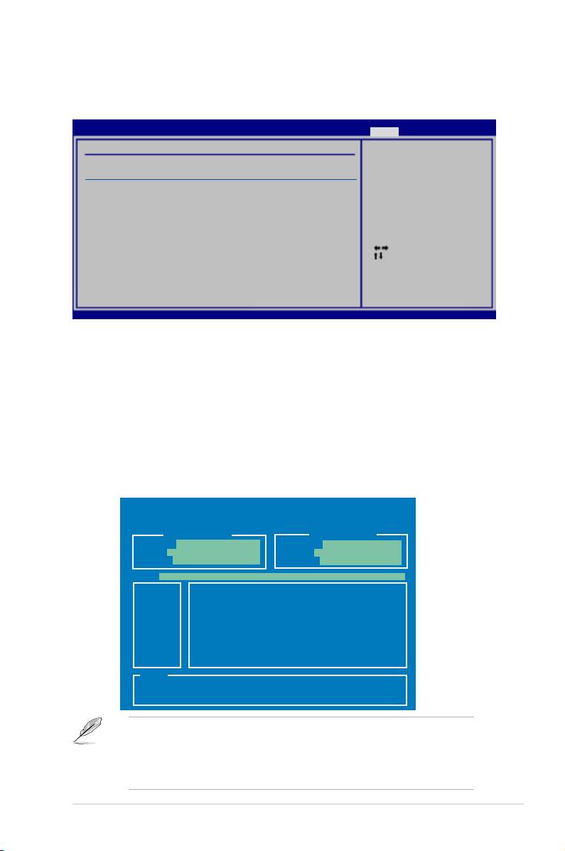
5.2.1 Running the support DVD
Place the support DVD to the optical drive. The DVD automatically displays the
Drivers menu if Autorun is enabled in your computer.
Click an icon to
display support DVD/
motherboard information
Click an item to install
If Autorun is NOT enabled in your computer, browse the contents of the support
DVD to locate the le ASSETUP.EXE from the BIN folder. Double-click the
ASSETUP.EXE to run the DVD.
ASUS P5E3 Premium/WiFi-AP @n 5-1

5.2.2 Drivers menu
The Drivers menu shows the available device drivers if the system detects installed
devices. Install the necessary drivers to activate the devices.
ASUS InstAll - Drivers Installation Wizard
Installs all of the drivers through the Installation Wizard.
Intel Chipset Inf Update Program
®
Installs the Intel
chipset Inf update program.
SoundMAX ADI1988 Audio Driver
®
Installs the SoundMAX
ADI1988 audio driver and application.
Marvell Yukon Gigabit Ethernet Driver
Installs the Marvell Yukon Gigabit Ethernet driver.
Realtek RTL8110SC LAN Driver
Installs the Realtek RTL8110SC LAN driver.
JMicro JMB36X RAID Controller Driver
®
Installs the JMicro
JMB36X RAID controller driver.
ASUS EPU Driver + AI Gear 3 Utility
Installs the EPU + AI Gear 3 driver.
Install this driver before the ASUS AI Suite utility.
ASUS WiFi-AP @n
Installs the ASUS WiFi-AP @n driver.
USB 2.0 Driver
Installs the USB 2.0 driver.
5-2 Chapter 5: Software support
