ASRock E350M1 – page 8
Manual for ASRock E350M1
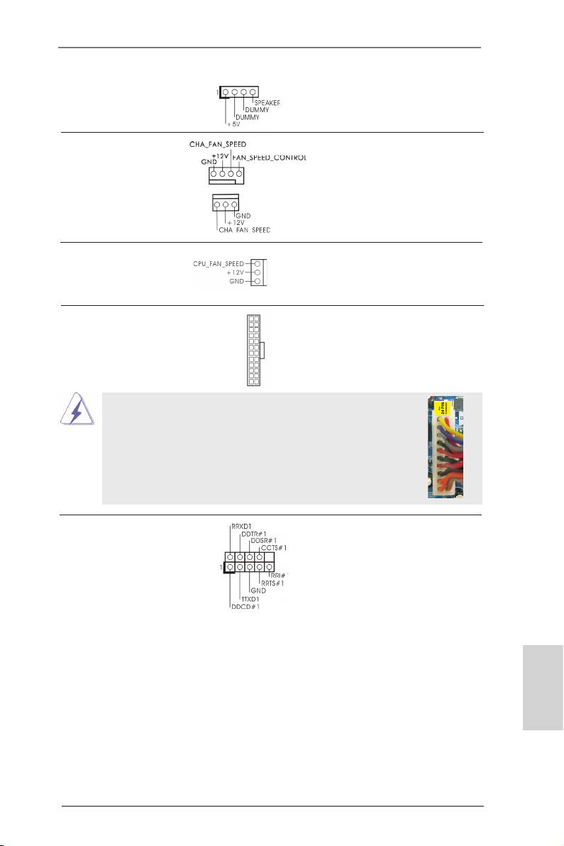
機箱喇叭接頭 請將機箱喇叭連接到這個接
(4 針 SPEAKER1)
頭。
( 見第 2 頁第 13 項 )
機箱風扇接頭 請將風扇連接線接到這個接
(4 針 CHA_FAN1)
頭,並讓黑線與接地的針腳
( 見第 2 頁第 2 項 )
相接。
(3 針 CHA_FAN2)
( 見第 2 頁第 14 項 )
CPU 風扇接頭 請將 CPU 風扇連接線接到這個
(3 針 CPU_FAN1)
接頭,並讓黑線與接地的針腳
( 見第 2 頁第 1 項 )
相接。
ATX 電源接頭 請將 ATX 電源供應器連接到這
12
24
(24 針 ATXPWR1)
個接頭。
( 見第 2 頁第 7 項 )
1
13
雖然此主機板提供 24-pin ATX 電源接口 , 但是您仍然可以使
12
24
用傳統的 20-pin ATX 電源。為了使用 20-pin ATX 電源 , 請順
著 Pin 1 和 Pin 13 插上電源接頭。
20-Pin ATX 電源安裝說明
1
13
序列埠 這個序列埠 COM1 支援一個序
(9 針 COM1)
列埠的裝置。
( 見第 2 頁第 21 項 )
繁體中文
141
ASRock E350M1 Motherboard

2. BIOS 訊息
主板上的Flash Memory晶片存儲了BIOS設置程序。啟動系統,在系統開機自檢(POST)
的過程中按下 <F2> 或 <Del> 鍵,就可進入 BIOS 設置程序,否則將繼續進行開機自檢
之常規檢驗。如果需要在開機自檢後進入 BIOS 設置程序,請按下 <Ctl> + <Alt> +
<Delete> 鍵重新啟動電腦,或者按下系統面板上的重開按鈕。功能設置程序儲存有主
板自身的和連接在其上的設備的缺省和設定的參數。這些訊息用於在啟動系統和系統
運行需要時,測試和初始化元件。有關 BIOS 設置的詳細訊息,請查閱隨機支援光碟
裡的使用手冊 (PDF 文件 )。
3. 支援光碟訊息
®
®
®
本主板支援各種微軟 Windows
操作系統:Microsoft
Windows
8/8 64 位元 /7/7
TM
TM
64 位元 /Vista
/Vista
64 位元 /XP/XP 多媒體中心 /XP 64 位元。主板附帶的支援光
碟包含各種有助於提高主板效能的必要驅動和實用程式。請將隨機支援光碟放入光碟
機裡,如果系統的“自動運行”功能已啟用,銀幕將會自動顯示主菜單。如果主菜單
不能自動顯示,請查閱支援光碟內 BIN 文件夾下的 ASSETUP.EXE 文件並雙點它,即可
調出主菜單。
繁體中文
142
ASRock E350M1 Motherboard

Installing OS on a HDD Larger Than 2TB
®
This motherboard is adopting UEFI BIOS that allows Windows
OS to be installed
on a large size HDD (>2TB). Please follow below procedure to install the operating
system.
®
TM
1. Please make sure to use Windows
Vista
64-bit (with SP1 or above),
®
®
Windows
7 64-bit or Windows
8 64-bit.
2. Press <F2> or <Delete> at system POST. Set AHCI Mode in UEFI Setup Utility >
Advanced > Storage Conguration > SATA Mode.
3. Choose the item “UEFI:xxx“ to boot in UEFI Setup Utility > Boot > Boot Option #1.
®
(“xxx” is the device which contains your Windows
installation les. Normally it is
an optical drive.) You can also press <F11> to launch boot menu at system POST
and choose the item “UEFI:xxx“ to boot.
®
4. Start Windows
installation.
®
5. If you install Windows
7 64-bit OS, OS will be formatted by GPT (GUID Partition
®
Table). Please install the hotx le from Microsoft
:
http://support.microsoft.com/kb/979903
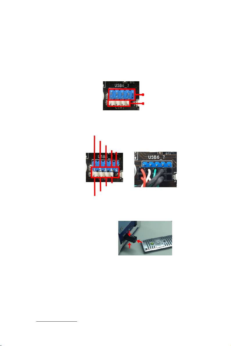
Remote Receiver Installation Guide
This motherboard is equipped with a 4-pin CIR header (CIR1, see page 2, No. 17),
which is used to connect the Remote Receiver. Please refer to below procedure for
installing the Remote Receiver.
1. Find the CIR header located under the USB 2.0 header (USB8_9, see page 2,
No. 18) on this motherboard.
USB 2.0 header (9-pin, blue)
CIR header (4-pin, white)
2. Connect the front USB cable to the USB 2.0 header (as below, pin 1-5) and the
CIR header. Please make sure the wire assignments and the pin assignments are
matched correctly.
USB_PWR
P-
P+
GND
DUMMY
GND
IRTX
IRRX
ATX+5VSB
3. Install the Remote Receiver to the front USB port. If the Remote Receiver cannot
successfully receive the infrared signals from the Remote Controller, please try to
install it to the other front USB port.
* Only one of the front USB port can support CIR function. When the CIR function is enabled,
the other port will remain USB function.
* The Remote Receiver is used for front USB only. Please do not use the rear USB bracket
to connect it on the rear panel. The Remote Receiver is able to receive the multi-direction
infrared signals (top, down and front), which is compatible with most of the chassis on the
market.
* The Remote Receiver and Remote Controller are not bundled with this motherboard and may
be sold separately in the near future. Please visit our website for further information:
http://www.asrock.com
